However, there are still advantages for doing so which include the ability to cut power to certain track to shut off the sound effects of engines parked on them; the ability to run conventional and command engines on the same layout in different sections without conflicting power signals; electrical troubleshooting; etc.
Most of this side of the layout will be one large electrical block all wired together because I doubt I could operate two or more trains on them at the same time. But, I did want the ability to kill power to various sections so that I could park several engines on the layout at once. So, each of the three sidings has its middle rail (hot) wired through a on/off toggle switch.
The main layout's bus wires are 14 gauge, and the track feeder wires are also 14 gauge. This is pretty robust wire and should be fine for such a small layout as mine. Per Lionel's own blog, they recommend 16g bus wires and 18g feeders wires which means my choices are a bit overkill. That is okay.
Using old flextrack is a real pain and requires a lot of finagling to assembly, frequently with a hammer. During the process the feeders I had attached to the underside of the rail would occasionally fall out. They snapped in once, but after that the rail spread enough that they wouldn't stay in after trying to jam them in multiple times. So, for a couple I also had to solder them in place from below. For others, I was more careful to to avoid unnecessary maneuvering of the track before attaching the wires.
All the same, if I discover a break in power in the future I can just solder a wire to the outside of the rail.
To remember where I dropped feeder wires I marked the locations with some beads painted either red or black and pinned to the track.
Then, I made a diagram of the layout to record this information on the off-chance that it might be useful someday. As can be seen I installed a LOT of feeders now, but I would prefer to avoid messing around under the layout in the future if there is a voltage drop. It doesn't show the isolated three sidings (in blue) because I haven't laid that track yet.
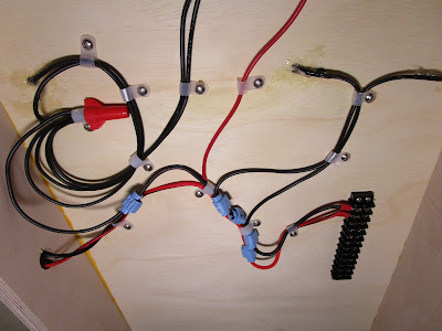
To join the feeders to the bus line I used 3M #560 insulation displacement connectors (IDC), otherwise known as "suitcase" connectors. Some people swear by them and others swear at them, but since I had a ton of them lying around I used them. I first confirmed on the 3M website that they were rated for 14 gauge wire on both sides.
The only complication is that because my mainline has multiple feeders to the same section of track there are places where the same rail is being fed from multiple connections to the bus wires. Normally this is a good thing, but with MTH's DCS system it can sometimes result in mixed-up signals. If you Google "MTH Star Wiring" you will find many pages online about it (including this one) and the solution around this is to make sure that each isolated section of track only has one set of feeders to it.
At this time I am not concerned with potential MTH DCS wiring problems. I don't have any DCS engines, and even if I did my layout is so small that the signals shouldn't get too confused. If it later proves to be a problem in the future I can deal with it then.
I do want the ability to use Lionel's Train Master Command Control so I will make sure that the inputs to my layout's wiring can be toggled for that, but I will discuss that more in the future.
The ends of the bus lines terminate at heavy duty, 20AMP block terminals. I found some 12-screw ones for less than $3 each on Amazon so I used them, though I doubt I will need all of those contacts. However, it gives me options for future wiring.
I also used caulk on the underside of the benchwork where the wires came through the plywood. This not only secured the wires further (in case Harrison wanted to yank them out) and it filled the hole up which would stop any glue mess from dripping down when I ballast the track later on.


No comments:
Post a Comment