Wednesday, January 29, 2025

C. P. Mandarin Orange Express boxcar #35893

Chinese New Year is January 29, 2025. For those wondering why I am mentioning it on a train blog, here is a brief railroad history lesson...

My wife first spotted a Micro Trains N scale car at a train show. She liked the way it looked, and I love oranges and Chinese history, so it seemed a natural purchase. I was a bit envious of the fact that it was for her N scale layout but that was okay. 

Then, at the Springfield train show I found an O scale model by MTH and I had to add it to my collection. I figured it would sort of fit the theme for my next layout (New England railroads, 1970s-1980), it was a true O-scale car, and the graphics looked even better in the larger scale. 

I became curious and wanted to learn more about the prototype. Digging around online, I found out that the popularity of Mandarin oranges in Canada is due to Japanese immigrants there who would receive gifts of oranges from their family back in Asia as part of the lunar New Year celebrations. Whole trainloads of insulated and/or heated boxcars carrying oranges would be shipped across Canada during the winter months from Vancouver to Toronto and Montreal which have large Asian population centers. 

In 1978, Canadian Pacific chose a single boxcar to paint in a one-of-a-kind scheme of black and white with orange slices. Each side was reversed, with the white artwork on one end and the black artwork on the other. It was usually located right behind the locomotives and C.P. featured it in a media campaign that year. Some additional interesting information about the Mandarin orange shipments can be found here and here.

For even more information, check out the book Canadial Rail Car Pictorial, Volume 1 (which features the car on its cover!):

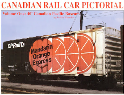
My O scale car was weathered to look like the the above picture. You will note that the artwork isn't perfect for the car, as there is an extra panel of white on the right-hand side. I think the oranges on the MTH car should have been wider, but I am not sure. However, unless you have the prototype picture next to it, you won't notice it. It is a fun car to occasionally pull out and run. 

As the Chinese say: "Gong xi fa cai" ("Wishing you Great Happiness and Prosperity").

Saturday, January 25, 2025

The problem of size

One of the issues I face as I plan my layout is just how much space O scale takes up. Mathematically, an O scale model takes up 8x as many space as its HO scale counterpart (2x longer, 2x wider, 2x higher). But my brain isn't experienced enough to think like that. For 30+ years I have modeled in HO or N scale, and I have a pretty good grasp of what I can do with those scales in a given amount of space. 

My O scale layout is 3' deep, which in HO scale would be a lot of space and in N scale it would be enormous. But to fit even a simple shed or structure (which could easily be 6" x 12" in 1:48 scale) takes up a lot of ground. It is deceiving. As a result, I am carefully planning where my industries will go and need to use mock-ups and foundation templates to truly get a lay of the land. 

Online pictures of commercial kits from Walthers and Atlas help, as they frequently give the foundation dimensions. I then draw them up full size on graph paper or photocopy them. I can push these templates around to visualize things, even if I decide later on to scratchbuild the structures. They are better than nothing.

But even that doesn't take into account the massive size of true 1:48 freight cars. As seen in one of the pictures, I also use actual O scale models to help plan clearances and track siding lengths. My 36" deep benchwork now seems a whole lot smaller. 

Thankfully, I have an assistant who loves to help me test things out. Harrison has taken a real interest in this layout (to be fair, he loves any train!) and I think he is just as excited as I am to see progress made.

Saturday, January 18, 2025

My crossing dilemma

I like diamond crossings, especially in industrial settings. They look neat and I made sure to incorporate one into my track plan. I will rarely be used and I added it more for its visual appeal than its operational potential, but it did actually have to function properly. Below is what I came up with.


I use Gargraves track and Ross Custom Switches, and RCS does make a 22.5-degree crossing. Unfortunately, it is ugly! The center has a large metal diamond casting held down by screws instead of individual rails. You can see in the picture below that there is just no graceful way to scenic it. I wanted to model this track partially buried in the dirt and weeds and there was no way to do that with that big frog casting. 


I understand that it is hard to fit three rails crossing three more rails in such a small footprint, especially since the outer rails need to be isolated from the inner rails to prevent short circuits. And you can't have the center pick-up roller drop down into gaps or lose contact either. 

So I talked with Steve, the owner of RCS, about this. I asked him if it was possible to remove the frog casting and then use a milling machine to remove portions of it so that it was less visually bulky. He thought it might work. (Note: I would never try that on a mainline crossing but for some slow-speed industrial track it might work.) But I had another idea to try first.

Atlas O also sells a 22.5-degree crossing. With its scale profile rails, more open appearance in the middle area, and smaller ties it looks a lot more realistic too. I found a used one on Ebay at a great price so I bought it to experiment with. I want to see if I can get it to work with my Gargraves track. The ties are smaller and spaced closer together so it doesn't match the surrounding track. But it presented me with a challenge: could I transplant the Atlas crossing (rails/frogs) onto new ties that were spaced like the Gargraves track?

You can see the Atlas crossing in front and regular Gargraves track in the back.


When I received it I noticed it was heavily used. Or maybe worn. Various areas were ground away and appeared light gray, which washed off like a powder. Perhaps it is the residue from plastic wheels banging into it. Also, it is made of at least four materials: plastic (ties), nickel silver (outer rails), copper/bronze alloy (center "X" rail), and some grayish-silver metal (the outer "v" rails"). It seems odd to use so many different materials.


I started by trimming off every other tie with rail nippers, and then used a chisel blade to carve away any remaining spike detail. 


I attempted to remove every other tie between the rails but all that did was cause one rail to pop out of the molded spikes. This required me to stop and repair it with superglue, and after that I decided to live with them. Moving on, I used stripwood to bulk out the ends of the ties. They aren't perfect but it was the best I could do. 


When it came time to wire it, I saved myself some wire and installed jumpers on the two outside rails for two of the legs. That resulted in me having only four feeder wires (one outer rail on each side, one middle rail on each side) of the two closest approach tracks. 


With the crossing flipped back over, I glued some thin stripwood onto the jumper with superglue to hide them. You can see one of my faux ties below, as it is the first tie to the right of the crossing guardrails. In the future I will plan where filler ties will go and then install the feeder wires between them.


Was the effort worth it? I think so. It looks a lot better than the Gargraves crossing and there is a lot more opportunity to scenic it. But it is a work in progress and I won't really know until it is finished.


Saturday, January 11, 2025

Wiring up the layout

Up until about 20 years ago most O scale layouts were wired up using block control and toggle switches, very similar to layouts in smaller scales. Then, Lionel released Train Master Command Control (TMCC) and MTH released Digital Command System (DCS) and things changed. Both of those systems (which aren't directly compatible) operate much like a DCC system in that it isn't necessary to divide a layout into isolated blocks.

However, there are still advantages for doing so which include the ability to cut power to certain track to shut off the sound effects of engines parked on them; the ability to run conventional and command engines on the same layout in different sections without conflicting power signals; electrical troubleshooting; etc. 

Most of this side of the layout will be one large electrical block all wired together because I doubt I could operate two or more trains on them at the same time. But, I did want the ability to kill power to various sections so that I could park several engines on the layout at once. So, each of the three sidings has its middle rail (hot) wired through a on/off toggle switch.

The main layout's bus wires are 14 gauge, and the track feeder wires are also 14 gauge. This is pretty robust wire and should be fine for such a small layout as mine. Per Lionel's own blog, they recommend 16g bus wires and 18g feeders wires which means my choices are a bit overkill. That is okay.

Using old flextrack is a real pain and requires a lot of finagling to assembly, frequently with a hammer. During the process the feeders I had attached to the underside of the rail would occasionally fall out. They snapped in once, but after that the rail spread enough that they wouldn't stay in after trying to jam them in multiple times. So, for a couple I also had to solder them in place from below. For others, I was more careful to to avoid unnecessary maneuvering of the track before attaching the wires. 

All the same, if I discover a break in power in the future I can just solder a wire to the outside of the rail.

To remember where I dropped feeder wires I marked the locations with some beads painted either red or black and pinned to the track. 


Then, I made a diagram of the layout to record this information on the off-chance that it might be useful someday. As can be seen I installed a LOT of feeders now, but I would prefer to avoid messing around under the layout in the future if there is a voltage drop. It doesn't show the isolated three sidings (in blue) because I haven't laid that track yet.


To join the feeders to the bus line I used 3M #560 insulation displacement connectors (IDC), otherwise known as "suitcase" connectors. Some people swear by them and others swear at them, but since I had a ton of them lying around I used them. I first confirmed on the 3M website that they were rated for 14 gauge wire on both sides.


The only complication is that because my mainline has multiple feeders to the same section of track there are places where the same rail is being fed from multiple connections to the bus wires. Normally this is a good thing, but with MTH's DCS system it can sometimes result in mixed-up signals. If you Google "MTH Star Wiring" you will find many pages online about it (including this one) and the solution around this is to make sure that each isolated section of track only has one set of feeders to it. 

At this time I am not concerned with potential MTH DCS wiring problems. I don't have any DCS engines, and even if I did my layout is so small that the signals shouldn't get too confused. If it later proves to be a problem in the future I can deal with it then. 

I do want the ability to use Lionel's Train Master Command Control so I will make sure that the inputs to my layout's wiring can be toggled for that, but I will discuss that more in the future.

The ends of the bus lines terminate at heavy duty, 20AMP block terminals. I found some 12-screw ones for less than $3 each on Amazon so I used them, though I doubt I will need all of those contacts. However, it gives me options for future wiring.

I also used caulk on the underside of the benchwork where the wires came through the plywood. This not only secured the wires further (in case Harrison wanted to yank them out) and it filled the hole up which would stop any glue mess from dripping down when I ballast the track later on.

Saturday, January 4, 2025

Organized chaos

Flextrack; cork roadbed; several types of caulk; caulking gun; Dremel tool; soldering iron station; lots of wire; various hand tools; multiple types of ballast; a couple of structure projects; various industry mock-ups; spray paint; glues; markers; assorted weights (gallon container, containers filled with lead shot); paper track templates; etc.


I love track laying, but it sure gets messy fast!