While building my model of Batten Kill Railroad engine #605 I came across references to the "Batten Kill Limited" and "Batten Kill Rambler" passenger excursion trains. I did some more digging and discovered that the the BKRR started the excursion train in 1984 using an Alco RS3 engine and two coaches. It was a start-up business and very small in scope, and they had to purchase a second engine just for it. The excursion train, known as the "Batten Kill Limited", and later the "Rambler", ran between Salem and Shushan and back. Sometimes it even ventured farther south to Cambridge. It was scheduled to run on Tuesdays, Thursdays, and the weekends... when the BKRR wasn't hauling freight. An online article about the train from June 18, 1984 The New York Times newspaper can be found here.
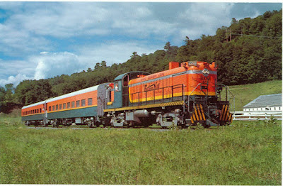
The image above is from a postcard dated 1984. Below is a similar shot from July of 1984. Look how brand new everything appears. There was a lot of pride in the appearance of the train.
.jpg)
Here is a shot dated July 31, 1984. One of the coaches (#8306) is painted yellow on the ends, a legacy from when it was part of the American Freedom Train. Friends of mine did research on this for an unrelated project and were unable to determine if the other coach also served in the Freedom Train or even what its original car number was. Why the BKRR kept the yellow paint is unknown.
It looks like recessed red marker lamps are on the ends of the cars too.

The two DL&W coaches were augmented and eventually replaced with some other stainless steel coaches. They even used a Budd RDC car (as a passenger car, not as motive power) for a time. At least one of the original DL&W coaches ended up lettereed for the Ontario Midland Railroad, as I have a slide in my collection from December 1986 showing it labeled "OMID". Its BKRR heritage is unmistakable. However, I it is suspected that it was just labeled as such during shipping and was never actually used by the OMID.
.jpg)
The October 1995 picture below shows one of the newer stainless steel cars coupled to the engine. The paint scheme on the newer cars was a lot more subdued, probably due to financial reasons and because painting the corrugated stainless steel side panels would be difficult. Only the window bands were done in orange, yellow, and green. More pictures of the stainless coaches can be found here and here. Also note that in the image below the large horn has been relocated to the top of the cab and what looks like a strobe light has also been installed.

The excursion train business lasted until the late 1990s but was eventually cancelled. The newer stainless steel cars remained on the property until at least 2002, but eventually they were sold to the Barnum & Bailey circus.
Modeling the original two-passenger car consist seemed manageable, so I started by reaching out to the DL&W Historical Society. They told me the two coaches were built by the American Car and Foundry in 1949, and they kindly provided me with an Erie Lackawanna car diagram for the coaches.
I looked for suitable O scale models but came up empty. The market is flooded with heavyweight coaches but not smooth-side cars. A couple of manufacturers make "shorty" (15" long) smooth-side cars but I didn't want to kitbash two together.
Someone in my TTOS Division informed me that K-Line made a lot of "Golden State" coaches... and EBay had a lot of them for sale Yay! After doing a lot of digging online I discovered that most of those 18" cars were for baggage cars, diners, Pullmans, sleepers, observation cars, domes, etc. Everything but plain coaches!
Pursuing other options, I researched passenger car kits. Some companies sell "Core kits" of cars that you can then customize with ends, roofs, and sides which match your particular model. They are a lot of work to put together if you want everything to look perfect, and they are designed for 2-rail O scale which means you need to modify the underframes for 3-rail trucks and couplers. Union Station Products sells core kits and sides for Erie Lackawanna coaches (#W47733 EL PS Smooth Side 62 Seat Coach). They aren't the exact cars I need but they are very similar. It features side skirts, but the website offers an option to order them without the skirts. In addition to the sides, I would need to purchase a core kit (#CK01 USP Core Kit ) for each car.
I then found an old kit from American Lightweight Car Company on Ebay for a 2-rail DL&W coach (#47733)... exactly what I needed! However, it looked like a lot of work to do, and it would still only get me half way there because I wanted a two coach train. But for $65 I bought it and stuck it in my stash just in case. In the end, I realized that despite being a fun project I just don't have as much free time as I used to so I sold it. (PS: shipping it cost nearly $60. I don't know why Ebay charged me only $12 for shipping to get it to me in the first place).

I then decided to look over the K-Line aluminum cars again. I discovered that the Rock Island Golden State observation car "Golden Divan" (#K4632-0479) had smooth sides, the correct window arrangement on one side and a pretty close window arrangement on the other, and end vestibule doors on one end only. Because K-Line over produced them, they were selling for under $40 complete with 3-rail trucks. The only obvious problems were that they were observation cars which meant that one end was entirely wrong, and a couple of windows on one side might not be correct. Further research showed that the observation ends are separate castings and easily removed. This gave me the confidence to start.
I bought three cars: two observations cars and one pullman car (which would be the source of the two plain ends) and got to work.

The trucks had a heavy layer of oil on the wheels so removed it with paper towels. Then, I removed the underframe casting with all of the "details" by undoing the screw on one end and the clip-in portion on the other end. They are generic castings but look better than nothing.

After removing some screws in the corners I was able to gentle slide out the flat metal frame which was a tight fit. The round observation casting ends required removing some more screws as well as cutting a pair of wires to the end-of-train light.

The body casting is extruded aluminum with tracks molded in the top for the lighting to clip to. I slid out the entire wiring board harness after disconnecting the wires. I wasn't sure if I wanted to add the lights back upon reassembly.

The interior casting is all wrong for coaches so I removed four tiny screws from underneath the car and took them out. I may replace it with casting featuring seats.

I was nearly done but I still had a problem. I needed two "flat ends" to replace the observation ends but I ordered the wrong third "donor" car. A baggage car or diner would have been perfect and I knew I needed one, but by mistake I stupidly I ordered a pullman car which only had one flat end casting.
I was afraid I would need to order a fourth car (grrr!) but a friend recommended the
Trainz website which had all of the K-Line spare parts. Trainz didn't have anything suitable (grrr!), but another friend told me that Lionel acquired the K-Line tooling and had parts. I looked online and found a flat end casting (huzzah!) in another color. Best yet, it was under $10 shipped. Unfortunately, upon receipt I discovered that the Lionel ends are
not interchangeable with the K-Line ones.
So, in the end (hardy har) I used a Dremel and microsaw to modify the extra K-Line end casting to work with my car. This involved cutting off the side vestibule doors and a couple of other things. Then, it was superglued in place and secured with weight until cured.
I took some 1/4" square styrene and superglued it into the corners of the vestibule so the sprung-loaded operating doors would permanently stay closed.
With the ends figured out, I turned my attention to the windows. One side of each car had correct window spacings, but the other side had two smaller windows and a round vent of some sort on the left end. I used clear plastic to mock up where I would need to cut new windows and fill existing holes if I wanted to make the sides accurate but in the end gave up the idea. I think trying to get the patches perfectly smooth on aluminum cars would be a lot of work. Besides, I can just run the cars with the accurate sides facing out!
Finally, I used a chisel blade to remove the glued on clear window glazing from the inside. I also scraped away any remaining glue reside which could prevent the new window glazing from lying flat.
To be continued...


.jpg)

.jpg)


